
How a Calculator Works
Ah, our good ol’ friend, the calculator. Whether loading some dubious games at home onto your TI-84 or making sure you haven’t lost your grasp on reality by punching in 2 + 2, your calculator has always been there to support you every step of the way. Sometimes, though, you might wonder at the exceptional amount of complexity stored into a (relatively) small device - how does it fit that admittedly shoddy but playable Tetris game into that medley of wires and electronic circuits? How can it tell me what 1/(7 * sqrt(2pi)) * e^(-0.5 * (x - 3) / 7)^2 is in a matter of milliseconds? To answer these questions and many other curiosities regarding our humble calculator, let us dive deep into its mechanics.
What’s In a Calculator?
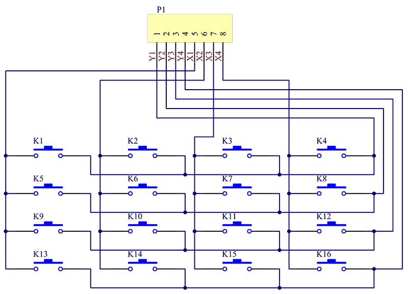
To first analyze the underlying workings of the calculator, we must dissect and understand its components. You can’t have anything electronic without a source of power, including calculators. Generally speaking, your more basic pocket calculators will run on a few cell batteries supplemented by a few solar cells, while your more advanced scientific calculators, like your TI-84s and TI-Nspires, will require several cell batteries or even the charge of an adapter. Perhaps the next most important component would be the keypad of a calculator, an array of rubber or plastic keys with various numbers or commands inscribed on them. When you press on a key, the circuit underneath it is completed, thus sending an electrical signal through the circuit board.
 (The upside-down T shape objects representing the individual keys.)
Your calculation is displayed through the topmost panel, which is generally an LCD display.
(The upside-down T shape objects representing the individual keys.)
Your calculation is displayed through the topmost panel, which is generally an LCD display.
 (A Texas Instruments calculator with the underlying LCD electrode shapes being revealed.)
Last but not least, the tiny but ever-powerful microprocessor temporarily stores the digits and various operations inside a register, converts the resulting binary output into a decimal representation, and shoots the result to the LCD. Other programmable devices, like your laptop, phone, or desktop, also have microprocessors - all on a small little chip.
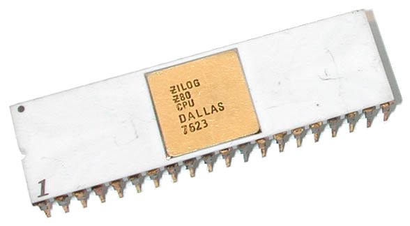 A Zilog Z80, the TI-84’s microprocessor. Manufactured in June 1976.
But what’s a microprocessor made of? To put it simply, it’s a CPU all etched on a tiny integrated circuit - a set of electronic components that are etched into a thin layer of silicon - thus creating a tiny “chip” that can do a ton of calculations in a blink of an eye. The most important component of said circuit is perhaps the transistor - a revolutionary electronic invention that has radically changed the world of electronics.
Transistors and Digital Systems
But why exactly are transistors so crucial to digital systems and electronics as a whole? Well, to find out, we must understand what exactly a transistor does - take a look at this small visual:
![]() You can imagine transistors as small gates that control the flow of electricity, with the presence of water being a “1” in the binary world with an absence being a “0”. Naturally, this allows for digital engineers to design convoluted systems with boolean logic, allowing them to encode in boolean logic that can be utilized to create logic gates that can perform Boolean operations, such as AND, OR, NOT, NAND, NOR, XOR, and XNOR. All of these gates are used extensively to construct impressively massive but simple digital circuits that help power our day-to-day lives, one of them being the humble calculator. In the past, engineers used hardware such as vacuum tubes or relays to represent these logical gates. However, these components were relatively large, energy-intensive, and prone to burning out rather swiftly. On the other hand, transistors are tiny, energy-efficient, and far more durable than their logical brethren.
You can imagine transistors as small gates that control the flow of electricity, with the presence of water being a “1” in the binary world with an absence being a “0”. Naturally, this allows for digital engineers to design convoluted systems with boolean logic, allowing them to encode in boolean logic that can be utilized to create logic gates that can perform Boolean operations, such as AND, OR, NOT, NAND, NOR, XOR, and XNOR. All of these gates are used extensively to construct impressively massive but simple digital circuits that help power our day-to-day lives, one of them being the humble calculator. In the past, engineers used hardware such as vacuum tubes or relays to represent these logical gates. However, these components were relatively large, energy-intensive, and prone to burning out rather swiftly. On the other hand, transistors are tiny, energy-efficient, and far more durable than their logical brethren.
 Vacuum tubes of various sizes.
Logic Gates and Binary Arithmetic
When you press the “3” button on your calculator, it interprets the input in binary as “11”. When the calculator finishes its calculations, it converts the final binary answer back into the decimal format - the number system that we use on a day-to-day basis. Now, let’s take a look at the underlying logic gates that help the calculator churn out these results. Note that a 0 usually represents a “low” voltage and a 1 represents a “high” voltage.
AND Gate
The AND gate takes in two or more arguments and returns a 1 if all of its inputs are 1s.

An AND symbol.
OR Gate
The OR gate is a little more generous - it’ll give us a “high”(usually denoted by a 1) output if 1 or more of its outputs is also high.
 An OR symbol.
NOT Gate The NOT gate, as you might’ve guessed, just provides us with the inverted input - if you throw in a 0, you’ll get a 1. Shoot in a 1, you’ll get a 0.
NAND and NOR Gates
The NAND and NOR gates are just the opposite versions of their respective counterparts. You might notice that their symbolic representations have a circle at the output - that denotes that the output is being “inverted.”

 The NAND(top) and NOR(bottom) symbols.
XOR and XNOR Gates
The XOR gate represents an “exclusive or” gate, which returns a “high” result only when the two inputs are different. As one might have realized by now, the XNOR gate simply returns the opposite of the XOR gate.

 The XOR(top) and XNOR(bottom) symbols.
Before we spend some time on how these logic gates are utilized in a calculator’s microprocessor’s arithmetic, let’s make sure we’re on the same page with regards to binary arithmetic.
The XOR(top) and XNOR(bottom) symbols.
Before we spend some time on how these logic gates are utilized in a calculator’s microprocessor’s arithmetic, let’s make sure we’re on the same page with regards to binary arithmetic.
The Binary Number System
We live in a base-10 number system - i.e, the system that we use on a day-to-day basis for denoting numbers with 10 digits. However, in the binary(or base-2 number system), only 0s and 1s are used. So how do we add “up” in binary? Simple:
| Binary | Digital |
|---|---|
| 0 | 0 |
| 1 | 1 |
| 10 | 2 (as with the base-10 world, when we run out of digits, we start at 0 again, but add “1” to the left.) |
| 11 | 3 |
| 100 | 4 |
| 101 | 5 |
As can be seen, as a number moves to the right in a binary number, each digit represents a value two times higher than the one to the left.
Addition
Binary addition works in just the same way as normal addition, except that we carry when we get a value of 2 instead of a 10.
Hence, we have in binary:
0 + 0 = 00
0 + 1 = 01
1 + 0 = 01
1 + 1 = 10 (we carry on a 2 and add 1 to the left. Hence we get “10”.)
Subtraction
Subtraction is just reversed addition, but we borrow(as we do in normal subtraction). Hence, we have:
0 - 0 = 0
1 - 0 = 1
0 - 1 = 1 (borrow 1 from the next digit)
1 - 1 = 0
The adder circuit adds two bits(i.e, single-digit binary numbers). You’ll see that it’s remarkably similar to the XOR gate - when we smash together 1 and 1, we do indeed get 0, but without the carry digit. So what’s another logic gate is necessary to represent the carry digit, if it exists? Let us momentarily read out the results:
Results of Binary Addition
________
0 + 0 = 00
0 + 1 = 01
1 + 0 = 01
1 + 1 = 10
_______
Note that the carry digit matches the AND gate, bit-for-bit! So that must imply that we have to use an AND gate alongside an XOR gate to receive a result for addition. Indeed, that much is true, and this is what the circuit looks like:
 A half-adder circuit. It is named as such because you can never get “11” from a half circuit, which makes it, well, half-complete.
So how do we complete the half-adder circuit? Well, by making it a full adder by connecting two half-adders like below:
 By slapping any number of adders together, we can add any number of bits in a ripple carry adder.
 (In here, we’re using 4 adders, so we can add together two 4-digit binary numbers).
However, there are several flaws regarding a ripple carry adder - the biggest one being that the other adders have to wait for the adders before it to supply in a carry for them to being calculating their own sum and carry bit, and this “lag” grows exponentially as we have more and more adders. Ouch. Not exactly the kind of speed we want for simple addition and multiplication.
Hence, the carry look-ahead adder was patented in 1957 by IBM(though anticipated several centuries earlier by Charles Babbage, the inventor of the idea of the first digital computer). The carry look-ahead adder essentially assigns the task of determining carries and carry calculations to a different circuit, which serves the results of its carries to each digit’s adder. The resulting circuit is a lot more sophisticated than its simpler brother, the ripple-carry adder, but it slices off a lot of time that would otherwise be spent waiting for the previous adders.
The multiplication, division, and exponentiation circuits are more intricate orders of magnitudes, but the individual logic gates are still utilized throughout the process - for example, multiplication can be implemented like how a grade-schooler would; all you need to do is add the partial sums resulting from the individual multiplications, and it is even simpler than regular multiplication. After all, each partial sum in the binary world is merely the shifted version of the multiplicand or just a bunch of 0s. Hence, you might apply a bunch of AND circuits to copy the 1s and 0s over, or use a combination of NAND and OR circuits to return all 0s.
 Hopefully, you’ve gained a greater understanding(and a greater appreciation) of the seemingly basic work that your lonely TI-84 or your more basic 4-function calculator can do for you in a matter of milliseconds. Make sure your calculator is fully charged and, to prevent losing it, always put your precious calculator back in its case.
If you enjoyed this article and want to learn more about how to get things done, check out our article on minimizing procrastination.